Wednesday, March 31, 2010

Solar Powered Robot – A different endeavor in the robotic spree


Robots aren’t new, off course not, courtesy- Japan! Take a look at this robot – a solar powered one that walks on four legs. These legs are arranged in a way that; the front one is up while the opposite rear one is “pushing” the body and making it to advance. The other front leg is on the floor and pulling the body. The rear leg is just going forward together with the opposite front leg. Is kind of hard to understand but basically it is a sequence.

Walking robot IV (the name), is an all terrain, four legged robot with no RCX and no sensors. Just one motor, gears, solar cell and the insect based green robot is ready to walk as long as the sun is there. Walking robot IV is a better version of it’s part III, better as in – the latter uses the legs but it uses the gears to be stable whereas the former ( the improved version) is much faster with rear legs longer than the front ones that enables it to move faster and the stability clause is also given due recognition. The best part is that it can walk anywhere, ranging from flat surfaces to rough terrains.

Tuesday, March 30, 2010

Robo-Bats With Metal Muscles May Be Next Generation Of Remote Control Flyers


Tiny flying machines can be used for everything from indoor surveillance to exploring collapsed buildings, but simply making smaller versions of planes and helicopters doesn't work very well. Instead, researchers at North Carolina State University are mimicking nature's small flyers – and developing robotic bats that offer increased maneuverability and performance.


Small flyers, or micro-aerial vehicles (MAVs), have garnered a great deal of interest due to their potential applications where maneuverability in tight spaces is necessary, says researcher Gheorghe Bunget. For example, Bunget says, "due to the availability of small sensors, MAVs can be used for detection missions of biological, chemical and nuclear agents." But, due to their size, devices using a traditional fixed-wing or rotary-wing design have low maneuverability and aerodynamic efficiency.

So Bunget, a doctoral student in mechanical engineering at NC State, and his advisor Dr. Stefan Seelecke looked to nature. "We are trying to mimic nature as closely as possible," Seelecke says, "because it is very efficient. And, at the MAV scale, nature tells us that flapping flight – like that of the bat – is the most effective."

The researchers did extensive analysis of bats' skeletal and muscular systems before developing a "robo-bat" skeleton using rapid prototyping technologies. The fully assembled skeleton rests easily in the palm of your hand and, at less than 6 grams, feels as light as a feather. The researchers are currently completing fabrication and assembly of the joints, muscular system and wing membrane for the robo-bat, which should allow it to fly with the same efficient flapping motion used by real bats.

"The key concept here is the use of smart materials," Seelecke says. "We are using a shape-memory metal alloy that is super-elastic for the joints. The material provides a full range of motion, but will always return to its original position – a function performed by many tiny bones, cartilage and tendons in real bats."

Seelecke explains that the research team is also using smart materials for the muscular system. "We're using an alloy that responds to the heat from an electric current. That heat actuates micro-scale wires the size of a human hair, making them contract like 'metal muscles.' During the contraction, the powerful muscle wires also change their electric resistance, which can be easily measured, thus providing simultaneous action and sensory input. This dual functionality will help cut down on the robo-bat's weight, and allow the robot to respond quickly to changing conditions – such as a gust of wind – as perfectly as a real bat."

In addition to creating a surveillance tool with very real practical applications, Seelecke says the robo-bat could also help expand our understanding of aerodynamics. "It will allow us to do tests where we can control all of the variables – and finally give us the opportunity to fully understand the aerodynamics of flapping flight," Seelecke says.

Monday, March 29, 2010

Miniature Autonomous Robotic Vehicle (MARV)


The miniaturization of electronic circuits revolutionized computers and consumer electronics and led to the dawn of the information age. Similarly, the miniaturization of mechanical systems is expected to launch revolutions in areas such as medicine, space exploration, and surveillance. Small mobile machines could one day perform noninvasive microsurgery, miniaturized rovers could greatly reduce the cost of planetary missions, and tiny surveillance vehicles could carry equipment undetected.

One of the developments at sandia national lab directed towards mechanical system miniaturization is the Miniature Autonomous Robotic Vehicle (MARV). MARV is the first vehicle of its kind built at Sandia and is one of the world's smallest autonomous vehicles, meaning that it contains all necessary power, sensors, computers, and controls on board. MARV is one cubic inch in size and is made primarily from commercial parts using ordinary machining techniques.

MARV employs two on-board sensors developed at Sandia to locate and track buried wires containing radio frequency signals. By measuring the relative strength of the signal at the two side-by-side sensors, MARV's on-board computer makes decisions and directs the two drive motors to steer towards the signal. Using these sensors and making a series of control decisions, MARV can sense a buried wire, home in on it, and follow the wire. MARV can easily carry other types of sensors as well.

Although MARV is built of commercial parts (except for the Sandia-designed sensor) and has limited maneuverability, it is a starting point in the development of miniature autonomous vehicles. In this capacity MARV has served as a testbed for evaluating critical subsystems of future miniature autonomous vehicles. This has led in part to the development and production of autonomous vehicles with greatly enhanced mobility, more intelligence, on board navigation and communication, the ability to act cooperatively and smaller size. This ongoing work at Sandia involves many of Sandia's areas of technical expertise and is directed towards the development of swarms of miniature autonomous vehicles capable of performing tasks that are difficult or impossible to do today such as locating and disabling land mines, detecting chemical and biological weapons, and verifying treaties.

Features

* Fully self-contained operation
* Volume of one cubic inch
* On-board computers, sensors, and control
* Ability to locate and track electrical fields
* Can carry a variety of sensors
* Built primarily from commercial parts

Mind-Boggling Medical Technologies

If tiny robots crawling along the inside of a blood vessel sounds like something from a sci-fi thriller, think again. Blood bots, along with other amazing medical technologies, are in development now and provide promise for early diagnosis and treatment of a variety of medical conditions. In the not-too-distant future, you or a family member may benefit from the medical advances on the horizon.
Note: Many of the innovations discussed are still in the early stages of development. MSN Health & Fitness does not endorse or recommend any products, treatments or procedures in this presentation.
Blood bots
A robot barely visible to the eye may make scalpels a thing of the past for biopsies and blood-vessel repairs. Surgeons first inject these mechanical critters into a patient's vein. Once the device is inside the bloodstream, operators use a magnetic field to guide the tiny robot—it's just 1 millimeter in diameter—to its destination. There the bot can clean plaque-filled vessels like a Roto-Rooter and can even slice off tissue for biopsies. Because the bot, also called the "ViRob," makes deep incisions unnecessary, it reduces recovery time for the patient. It's also possible that physicians may be able to direct the bot from a remote location to operate on patients in the comfort of their own home in the future. Oded Salomon, an engineer at the Technion-Israel Institute of Technology in Haifa, Israel, and the developer of the bot, has said he believes it will be in use by specialists within five years.

Sunday, March 28, 2010

Korea to build magic kingdom for robots


The robot magic kingdom will be part of a giant residential and industrial complex called Robot Land in Incheon, one of South Korea's largest cities and a major transportation hub.

According to the Robot Land Web site, the theme park will feature all manner of robot entertainment, including exhibitions of robot characters from films and cartoons; reconstructions of robot-oriented movie sets like "Minority Report," "I,Robot," and "Matrix"; a robotic-arm ride; an aquarium where visitors can watch and manipulate robotic fish; and even droid cashiers and performers.

A theme park shopping area will likely feature robots operating as cashiers.
(Credit: Robot Land)

After a bidding process lasting several years, the Korean government has just authorized Incheon to build the park, which will cost 784.5 billion won (about $687 million), with $596 million coming from private investors, about $46 million from the central government, and about $46 million from the local government, according to the Korea Herald.

Construction is set to begin this year and is expected to be completed in 2013, with some parts of the facility opening in 2012, officials from Korea's Ministry of Knowledge Economy said.

Besides rides and Robocop look-alikes, the roughly 110-acre Incheon Robot Land will house residential complexes, office buildings, a Seoul National University robotics research center, a stadium for robotics competitions, and robot-themed shopping centers. The entire Robot Land is expected to attract 2.8 million visitors annually, boosting the local economy by creating some 18,000 related jobs in the theme park alone, ministry officials said.

The robotics industry in Korea, considered a leader in the field, was valued at an estimated $770 million in 2009, according to Telecoms Korea, up about 10 percent from 2008. The country has spawned a number of notable bots, namely Hubo, a smiling, blinking humanoid with the face of Albert Einstein. Others include the Hoya mini firefighter helper bot and Mahru-Z, a housemaid bot that does laundry.

Friday, March 26, 2010

all you need to know about robots....

what's new from japan


snake-like robots

---
souryu
snake robots are also known as serpentine robots.
as the name suggests, these robots possess multiple actuated
joints thus mulitple degrees of freedom.
this gives them superior ability to flex, reach, and approach a
huge volume in its workspace with infinte number of configurations.
this redundance in configurations gives them the technical name:
hyper redundant robots. ideally, the future snake design will
consist of three degree of freedom stages - roll, pitch, and extension.
souryu or blue dragon, is a remote-controlled robot designed by
tokyo institute of technology's professor shigeo hirose.
the snake-like souryu crawls using six tracks, two on each
side of its three-part body. it is equipped with a camera
and microphone to search for victims, and can bend at
the joints or roll over on its side to maneuver through rubble.

---
ACM-R3
the first successful mechanical snake was also developed
by professor shigeo hirose.
the active cord mechanism consisted of 13-links.


spider-like robots

---
comet III
was designed by chiba university professor kenzo nonami, and
is part of a state-funded project to develop de-mining technologies
for afghanistan. four metres long and weighing one tonne,
the comet III walks on six sturdy metal legs.
an additional limb in front is equipped with a metal
detector and radar to find mines, while a second sprays
paint on the ground to mark the spot.


legged-walking robots

---
yambo III
one of the moving and task performing robots,
the legged-walking type, which has high terrain adaptability,
is yambo III. generally walking robots need so many degrees
of freedom (DOF) that robots become heavy and its mechanism
become more complicated. one of the effective solutions to
these problems is developing the robot with bipedal configuration.

---
morph 3
officials and researchers in japan, home to almost half
the world's 756,000 industrial robots, hope a new robot
industry will give the stagnant economy a boost.
japanese researchers want to advance the technology
by improving mobility or making robots more autonomous.
morph 3, a 38-cm-tall humanoid robot, tries to stand
after being laid on its back during an experiment at the
chiba institute of technology in narashino, chiba prefecture.
the project is a joint project between kitano symbiotic system
project and leading edge design corp.
athletic properties of the robot become the highest among
the same size robots in the world.
the robot appeared on the stage of robocup 2002 held in
fukuoka, japan.

---
cyclops
is an interactive human-shaped machine. the machine is
equipped with a single camera eye and a spinal column
structure. this work was developed for 'robot meme exhibition'
at the national museum of innovative technology and
emerging science, tokyo, in 2001. cyclops was shown in
september 2002at ars electronica center in linz, austria as a
part of its permanent exhibition.

---
DB
an expert in brain science, kawato developed the DB,
a humanoid robot that can imitate human action, based on his
knowledge that the cerebellum plays a key role in learning
and memory. however, the robot has managed to learn only
24 kinds of human action over three years.

---
atom
japanese researchers are advocating a grand project,
under which the government would spend 50 billion
yen a year over three decades to develop a humanoid
robot with the mental, physical and emotional capacity
of a 5-year-old human - the atom project.

'most of today's robots operate with a program written by
humans. in order to develop a robot that can think and
move like a 5-year-old, we have to first understand the
mechanism of how human brains work,' mitsuo kawato,
chief of the computational neuroscience laboratories
at the kyoto-based advanced telecommunications
research institute internationa said, admitting the difficulty
of his project. 'that will be equal to understanding
human beings.'

tthe project was inspired by the popular robot animation series
'tetsuwan atom' by the late cartoonist osamu tezuka
(unlike cartoonist tezuka's 'atom' character, known as
'astro boy' overseas, based on an image of a 9-year-old
boy, the atom project aims to create a humanoid robot
with the physical, intellectual and emotional capacity of
a 5-year-old that would be able to think and move on its
own). the researchers say it would help promote scientific
and technological advances in japan, just like the u.s.
apollo project, which not only succeeded in landing men
on the moon but contributed to a broad range of technological
breakthroughs - a project of this magnitude would inject
much-needed vigor into a nation depressed from years of
economic slump.

Wednesday, March 24, 2010

What is Advanced Robotics?

The term "advanced robotics" first can into use in the 1980s. It is used to define any sensor-based robots that attempt to mimic human intelligence. They are used in a variety of fields ranging from manufacturing, nuclear, construction, space and underwater exploration, and health care.

Popular culture is filled with advanced robotics. The robot on the television show Lost in Space and movie robots like Star Wars' C3PO and R2D2 were some of the first seemingly intelligent robots that average people were exposed to. In 1986, movie-going audiences met Johnny 5, the little autonomous robot from the movie Short Circuit. While all of these robots appeared truly autonomous, the robots themselves were largely a combination of puppetry and acting.

By the late 20th century, the science fiction of advanced robotics and the reality of it were beginning to overlap. Advanced robots of the 21st century are considered semi-autonomous. This mean that they are able to perform their tasks with a level of independence not found in automatic machines. Those called general purpose robots are able to perform their required tasks nearly independently. Some can recognize people or objects, talk, monitor environmental quality, pick up supplies and perform other useful tasks.

Robots are able to do these tasks through the use of a sensor. A simple example of this sensor is in room cleaning robots that bump a wall and understand to turn around and try another direction. Lawn mowing robots rely on underground markers to tell them this same information. Some of the most advanced robots are able to actually "see" through the use of infrared or stereo vision.

Some of the most advanced robotics of the 21st century are humanoid robots, meaning they resemble humans in their physical appearance as well as in their actions. They are considered autonomous because they can learn and adapt to changes within their environment. Johnny 5 is more of a reality in the 21st century than moviegoers of the 1980s could have imagined. Robots are being taught everything from how to load a dishwasher to mimicking facial expressions in response to particular types of human interactions.

One of the greatest feats of advanced robotics was seen in the rovers Opportunity and Spirit. Opportunity and Spirit landed on Mars in January of 2004 with the intention of completing an approximately 90-day mission. As of January 2009, five years later, they were still in operation. They landed on the surface with a precision unmatched in previous missions. They operate through communications with the National Aeronautics and Space Administration (NASA) and continue their missions through semi-autonomous interactions with the surface of Mars.

There were estimated to be about 3,540,000 service robots in use in 2006. At that time, there were an additional 950,000 industrial robots. In early 2009, Microsoft founder Bill Gates has predicted that every home will have a robot by 2025. Small robots like room sweepers and surprisingly complicated entertainer robots like Furby have been in homes since the 1990s. Given the advances even since those robots were introduced, the future of advanced robotics certainly seems boundless.

Monday, March 22, 2010

DC Motor-Driver H-Bridge Circuit


Description
Physical motion of some form helps differentiate a robot from a computer. It would be nice if a motor could be attached directly to a chip that controlled the movement. But, most chips can't pass enough current or voltage to spin a motor. Also, motors tend to be electrically noisy (spikes) and can slam power back into the control lines when the motor direction or speed is changed.

Specialized circuits (motor drivers) have been developed to supply motors with power and to isolate the other ICs from electrical problems. These circuits can be designed such that they can be completely separate boards, reusable from project to project.

A very popular circuit for driving DC motors (ordinary or gearhead) is called an H-bridge. It's called that because it looks like the capital letter 'H' on classic schematics. The great ability of an H-bridge circuit is that the motor can be driven forward or backward at any speed, optionally using a completely independent power source.

An H-bridge design can be really simple for prototyping or really extravagant for added protection and isolation. An H-bridge can be implemented with various kinds of components (common bipolar transistors, FET transistors, MOSFET transistors, power MOSFETs, or even chips).

The example provided on this page features:

* TTL/CMOS compatible Microchip or Maxim 4427A or 4424 MOSFET driver chips that protect the logic chips, isolate electrical noise, and prevent potential short-circuits inherently possible in a discrete H-bridge.
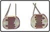
* Schottky diodes to protect against overvoltage or undervoltage from the motor.
* Capacitors to reduce electrical noise and provide spike power to the driver chips.
* Pull-up resistors that prevent unwanted motor movement while the microcontroller powers up or powers down.

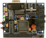
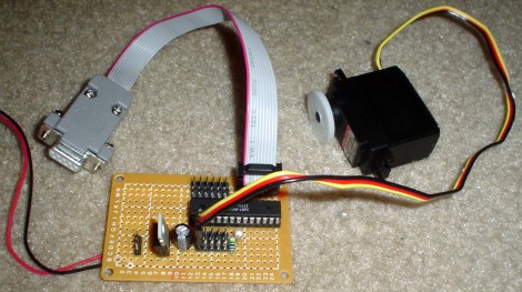
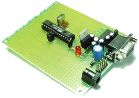
A diode-less version of this circuit successfully drove Bugdozer (http://www.robotroom.com/BugdozerBrains.html#HBRIDGE) to mini-sumo victory. The more robust (diode protected) version actually illustrated above is from Sweet, the line-following robot (http://www.robotroom.com/Sweet.html).

R1 and R2:

Two pull-up resistors (any value from 10 kilohm to 100 kilohm).

These make sure the inputs are both on unless a signal from the microcontroller tells one or the other to turn off. With both on or both off, the motor doesn't spin because there's no voltage drop between them.

Think of these as default values. Unless a different value is specified, the lines are pulled up. This means the circuit can come loose or be disconnected completely and the motor won't spin or stutter.

Technically, R1 and R2 could be eliminated, although then the motors are likely to jerk when the microcontroller powers up or powers down.
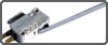
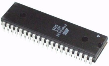

IC1:

TC4424 dual MOSFET transistor driver chip. (The MAX4427 and TC4427A is the same but with a lower amperage rating.) The DIP part can be purchased at Digi-Key as part #TC4424CPA.

WARNING:

Direct motor driving with this chip is only possible for motors that draw less than 100 mA (4427) to 150 mA (4424) under load. To determine if your motors qualify, use a multimeter to measure how much current your motor uses under load (for example, when actually driving your robot around) when the motors are connected directly to the battery (not through these chips).

This chip is not really supposed to drive a motor by itself. If you find the chip gets very hot and the motor doesn't spin (or barely spins or stalls when loaded) then you need to have the chip drive some real power MOSFETs like it is supposed to. Check out Figure 10-13 and Figure 10-15 on pages 186 and 187 of Intermediate Robot Building. It's not that much more difficult and it really makes a huge difference in performance.

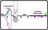
This chip provides two independent inputs that are compatible with CMOS or TTL chips. This circuit design uses IN A to vary power (on, off, or pulsed in-between) and IN B to determine direction.

OUT A follows the IN A signal but uses the full voltage from the power source, not the tiny voltage from the input signal itself. OUT B follows IN B in the same way.

For example, if IN A is turned on completely (2.4 volts or better) and IN B is turned off completely (0.8 volts or less) then OUT A turns on completely (up to 22 volts) and OUT B turns off completely (GND). The motor gets 22 volts.

This chip is constructed to protect the static sensitive MOSFETs, but also to protect the input sources from current being jammed back by the motors. Optoisolator ICs could be used at the inputs if greater protection and freedom from noise is desired.

Normally four transistors are needed in an H-bridge. Each transistor forms a corner in the letter 'H', with the motor being the bar in the middle. (See Figure 9-14 on page 158 of Intermediate Robot Building.) In this design, each output of the chip forms a complete vertical side of the letter 'H', with the motor still being in the middle. Because a side is now a single output, short-circuits can't form from the top of a side to the bottom of a side. No matter what the inputs, all power must travel from one side to the other -- through the motor.

A mechanical switch, relay, or logical gate could be used to turn the inputs on and off. It would work just fine at providing no movement (on/on or off/off), forward movement (on/off), or reverse movement (off/on). To provide power levels in between (like 50%), rapid pulses of on or off can be provided by pulse-width modulation using a chip or timer.

An important note regarding current rating: The plastic DIP package can only dissipate enough heat when the power usage is below 730 milliwatts. Therefore, it isn't possible to continuously run the chip at both the maximum voltage (22 V) and maximum amperage (3 A) rating. That would result in 66 watts of power usage. (That's 100x the maximum allowed.)


From: Paul Jurczak
Sent: Monday, March 12, 2001 10:59 AM
Subject: DC Motor-Driver H-Bridge Circuit

The actual DC power losses in the H-bridge would be:
I2 * (Rl + Rh)
= (3 A * 3 A) * (2.8 ohm + 2.5 ohm) = 47.7 W typical
and
= (3 A * 3 A) * (5 ohm + 5 ohm) = 90 W maximum

Which still is more than enough to melt this IC.

Paul.


I'm sincerely grateful for the feedback.

Paul is correctly pointing out that the chip only needs to dissipate the portion of power used in the chip's resistance.

For current to flow, the chip must have one gate high and one gate low. Therefore, Paul is adding the typical high and low resistance (from the 4427 datasheets) together to calculate the total amount of resistance the chip causes.

When a moving motor is added to the circuit, the motor uses up some (hopefully most) of the power. Just dive for that robot if the motors stall!

In summary, the chip can't run at maximum volts and maximum amps because most of the 66 watts (47 watts typical) would need to be dissipated by the chip.

Thanks Paul!


D1 and D3:

Schottky small-signal diodes.

I couldn't find any! So, I used 5817 Schottky diodes instead.

The key factors in substitution are:

* Are the diodes rated to turn on with less voltage than the TC4424's internal transistor base voltage? (600 millivolts)
* Are the diodes rated to handle the maximum reverse voltage? (22 volts)
* Are the diodes rated to handle the maximum current? (3 amps)

In the case of the 5817s, the datasheets answers are:

* Yes. (400 millivolts or less)
* Nearly. (20 volts -- so this is the circuit's new voltage maximum)
* Yes, peak (25 amps)

When a motor accelerates or decelerates for any reason (signal, load, or friction), there is reluctance for the electric field present in the motor coils to change. More properly, the changing field induces power. This "refunded" power can jam back into the chips.

D1 and D3 protect the chips from overvoltage by turning on when more voltage is coming from the motor than is coming from the batteries. The batteries absorb the power.

The turn-on rating of the diode must be lower than the turn-on rating of the chip, or else the diode won't turn on early enough to protect the chip.

Because the diode is installed in "reverse", the power can't flow from the batteries to the motors. If the diode was installed differently, power would immediately flow to the motors, bypassing the chip outputs (or worse, short-circuiting through the chip).

By the way, this arrangement is why the reverse or breakdown voltage of the diodes is important. If the reverse voltage rating was less than the full battery voltage, the battery would break down the reversed diode and just shoot through.


D2 and D4:

Schottky small-signal diodes.

D2 and D4 protect the chips from undervoltage (less than ground) by turning on when the voltage in the motor is below GND. Once again, the batteries take care of the problem, rather than power flowing backwards from the chip.

D1 through D4 could be eliminated. In fact, Bugdozer runs without the diodes. However, parasitic voltages can and do temporarily short power supplies (reset!) and can even destroy the driver chips.
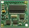
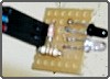
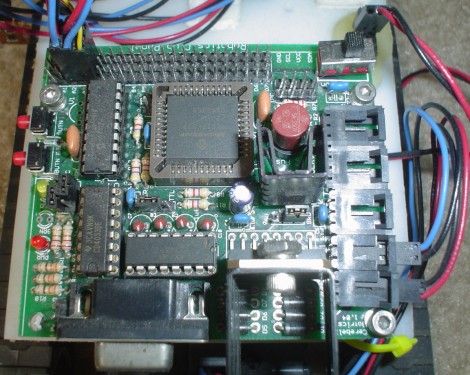
Despite what may seem complicated at first, the above photograph includes added features such as an LP2954 5V voltage regulator, a bicolor LED, and two switches for testing.

One H-bridge drives one motor. For a common two-wheeled robot, obviously two copies of the H-bridge circuit are needed.

* Pressing the right-side button makes the motor turn counter-clockwise and lights the LED green.
* Pressing the left-side button makes the motor turn clockwise and lights the LED red.
* Pressing both the buttons turns on the brakes (stopping the motor) and turns off the LED.
* Pressing the brakes quickly enough provides variable speed (between 0% and 100%).

Motor Speed Control


Description
This circuit will allow you to control the speed of an AC motor, for example an electric drill. The way that this circuit works is as follows. The bridge rectifier produces dc voltage from the 120vac line. A portion on this current passes through the 10K ohm pot. The circuit comprised of the 10k pot, the two 100 ohm resistors and the 50uf capacitors delivers gate drive of the SCR. The diode D1 protects the circuit from reverse voltage spikes. The ratings of the bridge rectifier and the SCR should be 25 amps and PIV 600 volts. The diode D1 should be rated for 2 amps with PIV of 600 volts. The circuit can handle a load up to 10 amps. The SCR should be very well heat sinked.

555 Based IR Proximity Detector


Description
Sometimes you want a simple solution to a problem and you don't mind if your main controller has to do the work. This IRPD requires the main robot processor to choose which side to look at, and requires it to "debounce" the results for reliably operation. But, it still works really well without any complex program code.

The NAND gate is a standard 74LS00 that you can get anywhere - even Radio Shack, same with the 555, IR detector (RS Everlight or Sharp GP1U58Y) and IR LEDs can also be gotten at Radio Shack. Parts are easy to find and simple to connect. This does not require any fancy wiring or parts placement. Make sure that you use a .1uf bypass cap next to the 555 and next to the IR demodulator. Tweak the 2K pot until you have 38KHz, if you have a 'scope, this is a 1/38,000 period, or about 26.3us. If you are using a Parallax Basic Stamp II for your robotic controller, you can feed the output of the 555 in an I/O port and measure the frequency very easily. The code to do this is below. It assumes that you are using port 7 as the 555 input port.

'Basic Stamp II Freq Counter
O555 con 7
freq var word


Loop:
count O555,100,freq
debug dec5 freq*10,cr
goto Loop


One of the nifty things that make the 555 circuit fun to use is that you can use it to do IR communications with other devices that read IR at 38KHz! If you run pin 4 of the 555 to a Stamp II port instead of just tying it high, you can use the serout Stamp II command to modulate the IR in such a fashion that other IR demodulator equiped devices can read it! I've done it, it works - Have fun.

Electronic Compass Controller


Electronic Compass Controller

Description
Eventually we all want to know just where our robot is, so we can choose an absolute direction. Usually this type of device is quite expensive. However to our rescue comes Dinsmore with low-cost electronic compass module. It outputs the four cardinal points and combinations thereof that will give eight directions. I decided that combining this with tilt sensors (the Dinsmore compass will only work if not tilted more than 12 degrees) would be a cool project. I am using a PIC 12C508 to do the dirty work and return an 8 bit number with the directional and tilt data all included. Here is the schemo that I am working with, I haven't yet found tilt sensors that I like so only the compass part has been implemented. Download from below the PIC source code for the 12C508 that will return the direction as a number from 0 to 7 in a single byte number at 2400 baud when the trigger line is cycled from a 1 to a 0 and back to a 1. Here is a Parallax Basic Stamp II program written to test the compass (download below as well). It has the compass connected to Port 2 and an LED connected to Port 0.

The compass works by sensing the active low reactions of the Hall Effect sensors and arranging them arbitrarily on the "map". The "<<" on my PC boards is the direction of the front of the robot, when THIS part of the board is facing North, the compass will return a 0; 1 through 7 are returned as you go around the compass to the East, South, West, etc. in 45 degree increments. So, your main controller can just multiply the number returned by 45 to get the compass points in degrees. The PIC takes two readings 1/3 of a second apart, if these readings differ it means that the compass hasn't settled yet. It will set bit 6 of the returned byte to show this along with the number of the last reading taken. For instance, if you are transitioning from North to North East, it will return 0x41, if you have settled on North East, it will return 0x01.

The nice part about this design is that a single line is used to start the reading and then read back the results! Very convenient, in my opinion. Below is the schematic, the PC board layout and a picture of how it lo

Homebrew Robots.

Homebrew robotics is a rapidly expanding subculture with a sizable Web presence. Amateur roboticists cobble together their creations using commercial robot kits, mail order components, toys and even old VCRs.

Homebrew robots are as varied as professional robots. Some weekend roboticists tinker with elaborate walking machines, some design their own service bots and others create competitive robots. The most familiar competitive robots are remote control fighters like you might see on "BattleBots." These machines aren't considered "true robots" because they don't have reprogrammable computer brains. They're basically souped-up remote control cars.

More advanced competitive robots are controlled by computer. Soccer robots, for example, play miniaturized soccer with no human input at all. A standard soccer bot team includes several individual robots that communicate with a central computer. The computer "sees" the entire soccer field with a video camera and picks out its own team members, the opponent's members, the ball and the goal based on their color. The computer processes this information at every second and decides how to direct its own team.


Adaptable and Universal
The personal computer revolution has been marked by extraordinary adaptability. Standardized hardware and programming languages let computer engineers and amateur programmers mold computers to their own particular purposes. Computer components are sort of like art supplies -- they have an infinite number of uses.

Most robots to date have been more like kitchen appliances. Roboticists build them from the ground up for a fairly specific purpose. They don't adapt well to radically new applications.

This situation may be changing. A company called Evolution Robotics is pioneering the world of adaptable robotics hardware and software. The company hopes to carve out a niche for itself with easy-to-use "robot developer kits."

The kits come with an open software platform tailored to a range of common robotic functions. For example, roboticists can easily give their creations the ability to follow a target, listen to voice commands and maneuver around obstacles. None of these capabilities are revolutionary from a technology standpoint, but it's unusual that you would find them in one simple package.

The kits also come with common robotics hardware that connects easily with the software. The standard kit comes with infrared sensors, motors, a microphone and a video camera. Roboticists put all these pieces together with a souped-up erector set -- a collection of aluminum body pieces and sturdy wheels.

These kits aren't your run-of-the-mill construction sets, of course. At upwards of $700, they're not cheap toys. But they are a big step toward a new sort of robotics. In the near future, creating a new robot to clean your house or take care of your pets while you're away might be as simple as writing a BASIC program to balance your checkbook.

Saturday, March 20, 2010

List of robot sensors, with detailed information and uses.
Click for a quick sensor reference guide.

Accelerometer Accelerometer
Detects motion, vibration, and angle with respect to gravity.
Advanced Sensor Interpretation Advanced Sensor Interpretation
Tired of sensor oscillation? Want higher sensor accuracy? Learn how to make a precision mathematical representation of any sensor.
Color Sensors Color Sensors
Learn how robots 'see' color, and how to build your own color sensors.
Current Sensor Current Sensor
Measure current and power use accurately with a current sensor.
Digital Compass Digital Compass
Detects orientation with respect to Earth's magnetic field.
Encoder (Slot, Rotary, Linear) Encoder (Slot, Rotary, Linear)
Used to determine translation distance, rotational velocity, and/or angle of a moving robot part. Also instructions on how to make your own encoder wheel.
Infrared Emitter/Detector Infrared Emitter/Detector
Emits and detects IR. Can be used for signalling, obstacle avoidance, and color detection.
Load and Torque Sensors Load and Torque Sensors
Measure torques and other forces directly for your robot system.
Mercury Tilt Switch Mercury Tilt Switch
A switch that gives a binary output, depending on the angle with respect to gravity, using mercury.
Photoresistor Photoresistor
Changes resistance with detected light. Can be used for simple robot behaviors, such as obstacle avoidance or photovores.
Robot Computer Vision Robot Computer Vision
Using a digital video camera with highspeed processing to detect the 'real world.'
SharpIR Rangefinder SharpIR Rangefinder
Detects obstacle range from inches to several meters. Modulated, hence immune to ambient IR.
Sonar Sonar
Detects obstacles and can determine object softness/hardness through echolocation.
Tactile Bumper Switch Tactile Bumper Switch
Detects physical contact, such as for robot collision detection.

introduction to microcontrollers....

Introduction to Microcontrollers

What are microcontrollers? They are what their name suggests. Today they can be found in almost any complex electronic device - from portable music devices to washing machines to your car. They are programmable, cheap, small, can handle abuse, require almost zero power, and there are so many variaties to suit every need. This is what makes them so useful for robotics - they are like tiny affordable computers that you can put right onto your robot.

Augmented Microcontrollers and Development Boards
In a pure sense, a microcontroller is just an IC (integrated circuit, or a black chip thing with pins coming out of it). However it is very common to add additional external components, such as a voltage regulator, capacitors, LEDs, motor driver, timing crystals, rs232, etc to the basic IC. Formally, this is called an augmented microcontroller. But in reality, most people just say 'microcontroller' even if it has augmentation. Other abbreviations would be ucontroller and MicroController Unit (MCU). Usually when I say 'microcontroller' what I really mean to say is 'augmented microcontroller.'

ATmega32 Microcontroller IC

As a beginner it is probably best to buy an augmented microcontroller. Why? Well because they have tons of goodies built onto them that are all assembled and debugged for you. They also often come with tech support, sample code, and a community of people to help you with them. My microcontroller parts list shows the more popular types that you can buy. They tend to cost from $30 to $150 depending on the features. This will give you a good introductory to microcontroller programming without having to be concerned with all the technical stuff.

Augmented Microcontroller

In the long term however you should build your own augmented microcontroller so that you may understand them better. The advantage to making your own is that it will probably cost you from $10-$30.

Make Your Own Microcontroller

Between getting a full augmented board and doing it yourself is something called a development board. These boards come pre-augmented with just the bare basics to get you started. They are designed for prototyping and testing of new ideas very quickly. They typically cost between $15 and $40.

Development Board

What comes with the IC?
There is a huge variety of microcontrollers out on the market, but I will go over a few common features that you will find useful for your robotics project.

For robots, ore important than any other feature on a microcontroller, is the I/O ports. Input ports are used for taking in sensor data, while output is used for sending commands to external hardware such as servos. There are two types of I/O ports, analog and digital.

Analog Input Ports
Analog Ports are necessary to connect sensors to your robot. Also known as an analog to digital converter (ADC), they recieve analog signals and convert them to a digital number within a certain numerical range.

So what is analog? Analog is a continuous voltage range and is typically found with sensors. However computers can only operate in the digital realm with 0's and 1's. So how does a microcontroller convert an analog signal to a digital signal?

First, the analog is measured after a predefined period of time passes. At each time period, the voltage is recorded as a number. This number then defines a signal of 0's and 1's as shown:
Analog to Digital Conversion Signal

The advantage of digital over analog is that digital is much better at eliminating background noise. Cell phones are all digital today, and although the digital signal is less representative than an analog signal, it is much less likely to degrade since computers can restore damaged digital signals. This allows for a clearer output signal to talk to your mom or whoever. MP3's are all digital too, usually encoded at 128 kbps. Higher bit rates obviously mean higher quality because they better represent the analog signal. But higher bit rates also require more memory and processing power.

Most microcontrollers today are 8 bit, meaning they have a range of 256 (2^8=256). There are a few that are 10 bit, 12 bit, and even 32 bit, but as you increase precision you also need a much faster processor.

What does this bit stuff mean for ADC? For example, suppose a sensor reads 0V to an 8 bit ADC. This would give you a digital ouput of 0. 5V would be 255. Now suppose a sensor gave an output of 2.9V, what would the ADC output be?

Doing the math:

    2.9V/5V = X/255
    X = 2.9*255/5 = 148

So how do you use an analog port? First make sure your sensor output does not exceed your digital logic voltage (usually 0V -> 5V). Then plug that output directly to the analog port.

This bit range could also be seen as a resolution. Higher resolutions mean higher accuracy, but occasionally can mean slower processing and more succeptability to noise. For example, suppose you had a 3 bit controller which has a range of 2^3=8. Then you have a distance sensor that outputed a number 0->7 (a total of 8) that represents the distance between your robot and the wall. If your sensor can see only 8 feet, then you get a resolution of 1 bit per foot (8 resolution / 8 feet = 1). But then suppose you have an 8 bit controller, you would get 256/8=32 ~ 1 bit per centimeter - way more accurate and useful! With the 3 bit controller, you could not tell the difference between 1 inch and 11 inches.

Digital I/O Ports
Digital ports are like analog ports, but with only 1 bit (2^1=2) hence a resolution of 2 - on and off. Digital ports obviously for that reason are rarely used for sensors, except for maybe on/off switches . . . What they are mostly used for is signal output. You can use them to control motors or LED's or just about anything. Send a high 5V signal to turn something on, or a low 0V to turn something off. Or if you want to have an LED at only half brightness, or a motor at half speed, send a square wave. Square waves are like turning something on and off so fast that its almost like sending out an analog voltage of your choice. Neat, huh?

This is an example of a square wave for PWM:
Square  Wave for Pulse Width Modulation PWM

These squarewaves are called PWM, short for pulse width modulation. They are most often used for controlling servos or DC motor H-Bridges.

Also a quick side note, analog ports can be used as digital ports.

Serial Communication, RS232, UART
A serial connection on your microcontroller is very useful for communication. You can use it to program your controller from a computer, use it to output data from your controller to your computer (great for debugging), or even use it to operate other electronics such as digital video cameras. Usually the microcontroller would require an external IC to handle everything, such as an RS232. To learn more, read my microcontroller UART tutorial.

Timers
A timer is the method by which the microcontroller measures the passing of time - such as for a clock, sonar, a pause/wait command, timer interrupts, etc. To learn more, read my microcontroller timer tutorial.

I^2C
I^2C (pronounced 'I-squared-C') is also useful for communicating, but I have never used it. Just make sure your controller has some method of communicating data to you for easy and effective debugging/testing of your robot programs. Its actually somewhat complicated, but usually the manufacturer has simplified it so all you have to do is plug-n-play and do a few print statements. To learn more, read the I^2C tutorial.

Motor Driver
To run a DC motor you need to either have an H-Bridge or a Motor Driver IC. The IC is great for small robots that do not exceed 1 or 2 amps per motor and the rated motor voltage is not higher than about 12V. The homemade H-Bridge would need to be used if you wanted to exceed those specs. There are a few H-Bridge controllers commercially available to buy, but usually they are way too expensive and are designed for battlebot type robots. The IC is small, very cheap, and can usually handle two motors. I highly recommend opting for the IC. Also, do not forget to put a heatsink onto the motordriver. Motordrivers give off pretty fireworks when they explode from overheating =)

Another interesting note, you can stack IC's in parallel to double the allowable current and heat dissipation. Theoretically you can stack as many as you want, as long as the current is high enough to still operate the logic of the IC. This works for voltage regulators too.

Output Indicators
Im referring to anything that can be used for debugging by communicating information to you. LED's, buzzers, LCD screens, anything that gives output. The better the indicator, the easier the debugging. The best indicator is to have your robot tethered and print or data log sensor and action data to your computer, but it isn't always possible to have your robot tethered.

Programming Languages
The lowest form of programming languages is the machine language. Microcontrollers need to be programmed with this.

An example of machine language:

    3A 10 51
    E6 DF
    32 38 00

Obviously neither of us could ever memorize what all those seemingly random numbers and letters do, so we would program in a higher language that makes much more sense:

    If (language = = easy)
    print "yay!";

These higher languages would then be compiled automatically into a machine language, which then you can upload into your robot. Probably the easiest language to learn would be BASIC, with a name true to itself. The BASIC Stamp microcontroller uses that language. But BASIC has its limitations, so if you have any programming experience at all, I recommend you program in C. This language was the precurser to C++, so if you can already program in C++, it should be really simple for you to learn. What complicates this is that there is no standard to programming microcontrollers. Each has its own features, its own language, its own compiler, and its own uploading to the controller method.

This is why I do not go into too much detail because there are too many options out there to talk about. The support documents that come with the controllers should answer your specific questions. Also, if you decide to use a PIC, understand that the compiler program (at least the good ones) can cost hundred of dollars. Most microcontrollers also require a special interface device between your computer and the chip for programming which could also cost from $10-$40.

fuzzy logic....

Fuzzy Logic Background
Computers define EVERYTHING in binary, a simple 0 or 1. Its either on, or off. But the world isnt black and white, and not everything is simply true or false.
Fuzzy Logic (FL) is a numeric representation where the answer isn't just Yes or No, but a grey Maybe. It isn't where something is just very hot or very cold, but instead could be luke warm, slightly chilly, etc. Humans operate much better when fuzzily describing things, instead of simply using black and white for everything. If we describe a temperature we might say 73 F, describing a food we might say its a little tastey but could be better, or naming a color we might say dark green or light green. To not have that range of descriptions would really hamper our descriptive abilities.

If robots are to ever out-perform humans, they need this ability too.

Disadvantages of Binary Logic
If a robot can only make decisions based on two extremes, its actions will also be two extremes. Its like saying a robot can only go two speeds, 1mph and 30mph, and no speed in between. If suppose your sensors give you values right between both extremes, your robot would become very jerky bouncing between both those speeds. This is referred to as oscillation, or when sensor data quickly bounces between two different case-based (pre-defined) actions.

case based example:

    sensor data can range between 0 and 255
    sensor value bounces between 127 and 128 (middle of range)
    10 is a made up tweak constant

    case based pseudocode:

      if (0->127)
        go 1mph
      if (128->255)
        go 30mph

(note: On an 8 bit analog-to-digital converter, 127.5 is not possible)

Case-baseed oscillation is very bad for your robot - jerky motions can quickly wear and break mechanical parts, and will waste huge amounts of energy in acceleration/deceleration. You could perhaps write a long cased-based list of sensor to speed conversions, but that would be painfully long, and will waste memory space and processing time.

Oscillation in Cased-Based Control

This is where fuzzy logic comes in, as fuzzy control allows very smooth transitions between actions with less code.*See Below

fuzzy logic example:

    sensor data can range between 0 and 255
    sensor value bounces between 127 and 128 (middle of range)

    fuzzy based pseudocode:

      speed = sensor/10

    so on a scale of 0mph to 30mph:

    if say your sensor = 127, speed = 12.7 mph
    and if sensor = 128, speed = 12.8 mph

(Note: So this above example isnt exactly fuzzy logic, but an oversimplified equation so that you can have a basis of understanding the later equations in this tutorial. This equation can be considered fuzzy logic if all added arbitrary weighted values equal 1, as explained later.)

Not only is there a smooth transition between speeds, but the fuzzy program was much shorter and easier to write too! There are many other advantages.

Advantages of Fuzzy Logic
It is inherently robust since it does not require precise, noise-free inputs. This means you can fudge (mmmmm . . . fuuuddggee) your equations with additional arbitrary constants in your equation.

New sensors can easily be incorporated into the system simply by generating appropriate governing equations. Often you can combine these equations into one.

Any number of inputs can be processed and outputs generated. Fuzzy logic is not limited to a few feedback inputs and one or two control outputs, nor is it necessary to measure or compute rate-of-change parameters in order for it to be implemented. Any sensor data that provides some indication of a system's actions and reactions is sufficient. This allows the sensors to be inexpensive and imprecise thus keeping the overall system cost and complexity low.

Fuzzy logic can control nonlinear systems that would be difficult or impossible to model as case-based. Fuzzy controllers are far simpler than knowledge-based systems. You do not need to be a controls expert, or fully understand the physics of your robot, to design a fuzzy logic control system.

Just like in PID control, fuzzy logic can be "tweaked" once the system is operating in order to optimize performance. Generally, fuzzy logic is so forgiving that the system will probably work the first time without any tweaking.

Fuzzy logic in most cases takes up significantly fewer lines of code in programming. Having memory issues? This may be your solution.

A disadvantage . . . There are exceptions to where case based programming is simpler to implement than fuzzy logic, such as when your mechanism can only work at a set of fixed outputs. Two examples would be gear changers, and navigating to fixed locations of objects centered around a robot arm. The following algorithms would still be possible, just highly complex and therefore not recommended. You can also use both methods, just mix and match to take only advantages of both.

Fuzzy Squirrel

Defining Fuzzy Logic With a Microcontroller
Most sensors used in hobby robotics operate on analog voltages, meaning that they output a fuzzy value between 0 and 1 (0V and 5V). This output then goes to your microcontroller's analog to digital (ADC) converter. The typical microcontroller uses an 8 bit ADC, which basically means it has a fuzzy range of 0 to 255 (0 being 0V and 255 being 5V). What exactly that 8 bit value means greatly depends on what your robot sensors are and sense, so you would then need an equation to convert that 0-255 value into something more meaningful - a color of an object, a distance to a target, a sound amplitude, etc.

You would then put that number into another equation (usually just multiplied or divided by some user defined tweak constant) to be applied to the robot actuators. As shown in the fuzzy logic example above, this process is fairly simple.

Example of Fuzzy Logic
A photovore robot would make a good example for fuzzy logic. Your robot reads in sensor values, plugs those values into an equation, then takes the new values and sends them to the motors.

This conceptual robot has two photoresistors plugged into two ADC:

    read left_sensor;
    read right_sensor;

    left_motor_speed = right_sensor * arbitrary_constant;
    right_motor_speed = left_sensor * arbitrary_constant;


So basically, the more light a sensor gets, the faster the opposite side motor goes - making the bot turn into the light. Just 4 lines long! If/then statements are typically many more, and dont work so well.

The above example has a flaw though, in that if the robot is in a dark area neither motor will work. Another better example:

    read left_sensor;
    read right_sensor;

    left_motor_speed = (left_sensor - right_sensor) * arbitrary_constant;
    right_motor_speed = (right_sensor - left_sensor) * arbitrary_constant;


Still, only four lines of code, yet the robot can track any light at any brightness level. The above equation still has an oscillation problem when both sensors bounce near zero, and the robot wont move if both sensors are zero, but fiddling with the arbitrary constant and adding additional parts to the equation will solve all of that.

One last example, but one of many solutions:

    left_motor_speed = (left_sensor - right_sensor) + arbitrary_constant/(right_sensor+1)^2;
    right_motor_speed = (right_sensor - left_sensor) + arbitrary_constant/(left_sensor+1)^2;

Mixing Digital and Analog Sensors
Because fuzzy logic is great for sensor fusion, I should show you how to mix analog and digital sensors.**See Below Starting with the simpler above photovore code, lets add something in front of our equations to represent digital collision sensors. This new code will allow the photovore to back away intelligently during wall collisions.

    left_motor_speed = (left_bumper*(-100)) + (left_sensor - right_sensor) * arbitrary_constant;
    right_motor_speed = (right_bumper*(-100)) + (right_sensor - left_sensor) * arbitrary_constant;

Now if the bumper doesnt detect a wall (bumper = 0), then the algorithm acts like normal because the first term is zero. But if bumper=1 (wall collision), that first term becomes -100, meaning the motor will suddenly back up and away from the wall. You can also add a time delay in the code so the bot will back up for X amount of time, but for simplicity Id just add a resistor/capacitor on the sensor with X time constant. As you can see, no additional lines of code were added (other than read the new sensors). Its also no longer pure analog, but now has digital components too. Hows that for sensor fusion? ;)

Note that you could use other digital sensors, such as sonar or encoders, in a similar way. You only limitation is how mathematically clever you are . . .

Negative Values in Fuzzy Logic
Some robot sensors, such as torque cells, give both positive and negative outputs. Now you may be thinking, 'I can only use 0->255, what if I want to include negative values?' Well, your equation could scale your range into the negatives.

negative conversion example:

    long signed int sensor_value; //variable type allows negative values in code

    sensor_value=-255/2; //shifts everything into the negative, where 127 is 0

There are many other ways to do this that I wont get in to, but you get the idea. For further reading check out the programming variables tutorial.

What if your sensor returns positive AND negative voltage values? Then set your microcontroller ground to 0V and your sensor ground to 2.5V (by using a voltage regulator). This way anything below 2.5V represents a negative value, and anything above it represents a positive voltage. Make sure your sensor output values are between 0V to 5V or you may damage the ADC. To do this, carefully scale a non-inverting amplifier with the right resistor values and place between your sensor output and the ADC input.

*Addendum on the Definition of Fuzzy Logic
Many will argue that the above description is a very poor description of true fuzzy logic, and they are correct. Fuzzy logic was never developed or intended for use on robots. Its use was for describing things that didnt fit a binary description. As such, this is not true fuzzy logic. However . . . The point of this tutorial is to adapt fuzzy logic into a functional, practical, shortened control algorithm that you may use on your robot. All equations do fit the definition of fuzzy logic, despite being permutated and rewritten into more useful (yet non-standard) notation.

**Addendum on Analog Computers
Some may also argue that this is only an analog computer, of which they are partially wrong. Many of the examples I gave use analog sensors, and have analog outputs to analog motors. In those cases, yes, it could be considered an analog computer. But what about the case where I use an on/off switch? Or what about a case of using binary solenoids for output, instead of motors? This cannot be argued to be an analog computer in every case.

Thursday, March 18, 2010

Robotic Prostatectomy: What Happens When Robots Fail

Also known as Robotic Assisted Laparoscopic Prostatectomy, robotic prostatectomy is a
minimally invasive type of prostate cancer surgery that utilizes a robotic surgical unit
called the da Vinci system. This prostate surgery is a revolutionary and advanced
procedure that profoundly reduces blood loss, pain, recovery time, hospital stays, trauma
to surrounding tissue and the drastically reduced side effects of other treatments such as
incontinence and sexual dysfunction.
In robotic surgery, the surgeon performs the procedure at a console 10 feet away from the
patient. From the console, the surgeon’s movements are communicated to the tip of
robotic hands. With the use of the da Vinci robot, robotic prostatectomy patients not only
have a better cure rate, there is less blood loss and need for transfusions. Additionally,
hospital stays are shorter. Most importantly, since the nerves are spared in this type of
procedure, there are fewer incidences of incontinence and impotence, which allows for a
better quality of life.
However, while each patient case is individual and their recovery is different, the
experience of the surgeon is of paramount importance. This is crucial for those rare
instances when the robot fails to perform and the surgeon then has to switch over to
traditional open or laproscopic expertise to complete the surgery. This arsenal of
experience is important not only for this procedure, but in other surgeries. The da Vinci
robot, which costs an estimated $1.5-1.8 million dollars, will soon be used in bladder and
kidney removals and hysterectomies. Since the learning curve for robotic surgeries is so
steep, the versatility of experience is the key to success in successful prostate removal
surgeries.

Saturday, March 13, 2010

Robot is a term with which almost all of us are quite familiar with. But most of us are unaware
about the technical insights or aspects about these wonders of electronic trade. A robot is
defined as reprogrammable, multifunctional manipulator, designed to move materials, parts,
tools, or specialized devices through various programmed motions for the performance of a
variety of tasks. It has a mechanical body and an electronic nerve system to drive it.
But the robot cannot perform task on its own. It does not have brain as we human being do. So
how does a robot work? For a robot to do something as desired and useful, we need to program
it with some kind of intelligence. This can vary from hardwired logical circuits implementing
some low-level reflex code to microcontrollers. In an advanced robotics systems, the control
system can go up to neural network control systems running on powerful microcomputers
networked together.
When someone decides to build a robot, the first thing that he would need is a robotic kit. Now
the question arises what is a robotic kit? A robotic kit is your blueprint and comprises of all the
tools and parts that a person would need for building a robot. Robotic kits are available online
along with manuals and robotic books which are of great help in building a robot. These robotic
kits are available in various dimensions, depending on the customer's requirement.
The robotic kit includes the mechanical parts required for building a robot like metal or plastic
parts, and mechanical components. The key components of robots have the ability to perform
repetitive tasks in a precise manner. Robots can be either industrial or domestic depending upon
the type of function they are required to perform. On a general note robots have found their
application in many fields such as Commerce, home security, medical field, industry, and
transportation
Learn more about robotics and robot kits at .http://www.robotshowto.com/

robotics - how to step into the virtual world...?


yes i would say it is a virtual world of making something realistic. its amazing that so many brialliant minds work in the virtual universe of creating a new life form....although rudimentary at first like all hand-crafted art...they will gradually become complex & wonderful.
robotics comprises atleat 4 major branches of learning:
* electrical engineering
* mechanical engineering & instrumentation
* computer science
* electronics
* arts (style, design & creativity)
you don' need to be an expert in all these feilds in order to build a decent robot.
but in the way of creating one, you'll learn many things from all these fields.
in this procedure u'll have to hone up your talents....adapt to new techniques & improvise your skills
think of renaissance scientist & artist leonardo da vinci. if he were around tday, he would be making robots.


vice-president's letter.-- first post.

dear bloggers,

we are glad to present this blog to all the robotic enthusiasts. i do not think that there is a need for any formal robotic-historical introduction.
this blog is fairly intended to present technological posts to the readers.

the blog administrators will try their level best by providing the best programs, circuit designs & ideas.
any suggestions, queries are always welcome.

we hope that this blog will help all the robo-enthusiasts.

thanking you.

A. Ravi sasanka
vice-president
ircs.